When I built my desktop PC a few years ago, I opted for the cheapest mainboard that would still satisfy my needs. After all, it essentially has the same components and does the same things a more expensive brand does. The result of my frugality, the Biostar B350ET2 is working fine so far, but there is one thing I’ve regretted ever since I used it for the first time: the firmware really sucks. Especially the BIOS menu shows how Biostar can be way cheaper than other more established brands. The worst part about the firmware is the fan controller though. I’ve probably spent around six days by now, trying to figure out the various settings, thresholds, sensitivity values and what not but my fans would never behave the way they’re supposed to.
Initial “design”
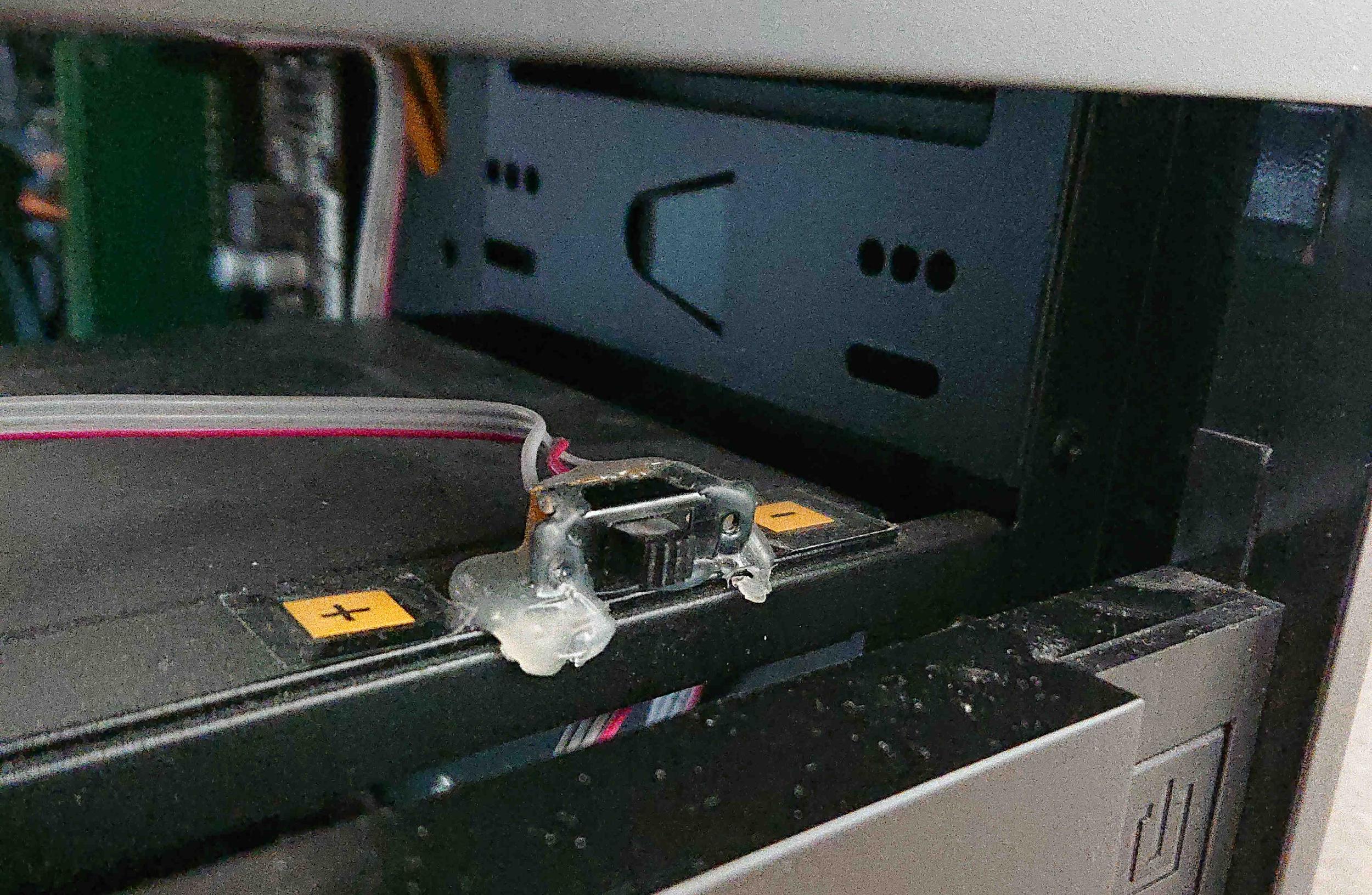
Out of sheer desperation I made a quick and dirty mod by fitting a two-way switch to the front of my PC case that switches fan supply power between 5 and 12 volts, thus reducing the speed considerably whenever I don’t need a lot of cooling. Of course, I occasionally forgot to switch to the higher cooling mode when doing high performance work and as a result, my AMD GPU — not exactly renowned for their thermal performance — heated up the whole PC until the thermal safety shutdown triggered and everything went black. I finally was fed up enough to build something a little more sensible.
Design decisions
I have two Arctic 120 mm case fans in my desktop. One intake in the front and one exhaust in the back. Luckily, they are PWM controllable. First, I needed to decide on a way to obtain a usable metric for gauging the fan speed:
- I didn’t want to fit a temperature sensor, mainly because sourcing electronic parts locally requires a three hour bike ride and ordering online would just take too long for my impatient soul.
- I could have tapped into the mainboard’s temperature sensors but that would’ve required to essentially dismantle the whole PC so I can solder on both sides of the mainboard.
- Instead of tapping into the mainboard’s temperature sensors, using the PWM signal from the mainboard itself would have worked and required a lot less hassle, but due to the quality of the firmware, I wasn’t so sure of its usefulness.
I didn’t really like any of those options. I realized that the only component getting hot enough to heat up the whole case is my GPU and as it is an AMD GPU it can easily reach around 85 °C when maxed out. Coming in second is the Ryzen 5 2600 CPU. It is fitted with its own active cooler, though and usually doesn’t heat the case up too much. Therefore, I opted to set the case fan speed based on the GPU fan speed. For good measure, the CPU fan speed is included as well.
I could have quite easily just used the raw PWM signal from the GPU fan controller and fed that into my case fans. However, that way there is less control about the actual speed as different manufacturer’s fans reach different speeds. Additionally, I really wanted to incorporate the CPU fan speed as well. Thirdly, having gone the quick and dirty way for my first “fan controller”, this time I elected to build a more sound solution. I decided to assemble a small PCB with PWM inputs and outputs and a MCU to control it all.
Acquiring data
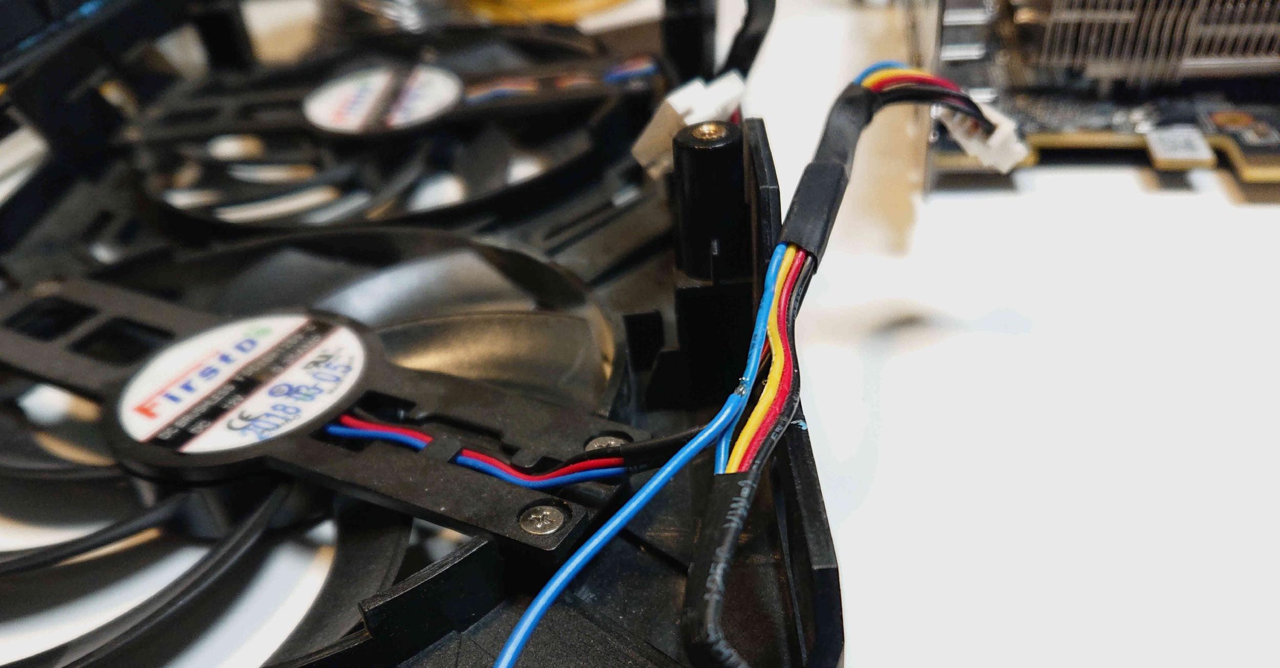
Getting the PWM signals was sorted out rather quickly. I took off the video card fan shroud and tapped directly into the fan wires. This way I didn’t have to remove the heatsink itself, although soldering directly onto the PCB would have been a little bit nicer. At the time I thought the tachometer line might become handy later one, but in hindsight the PWM signal was enough. Lots of hot glue keep the wires in place and a little JST plug is just good practice.
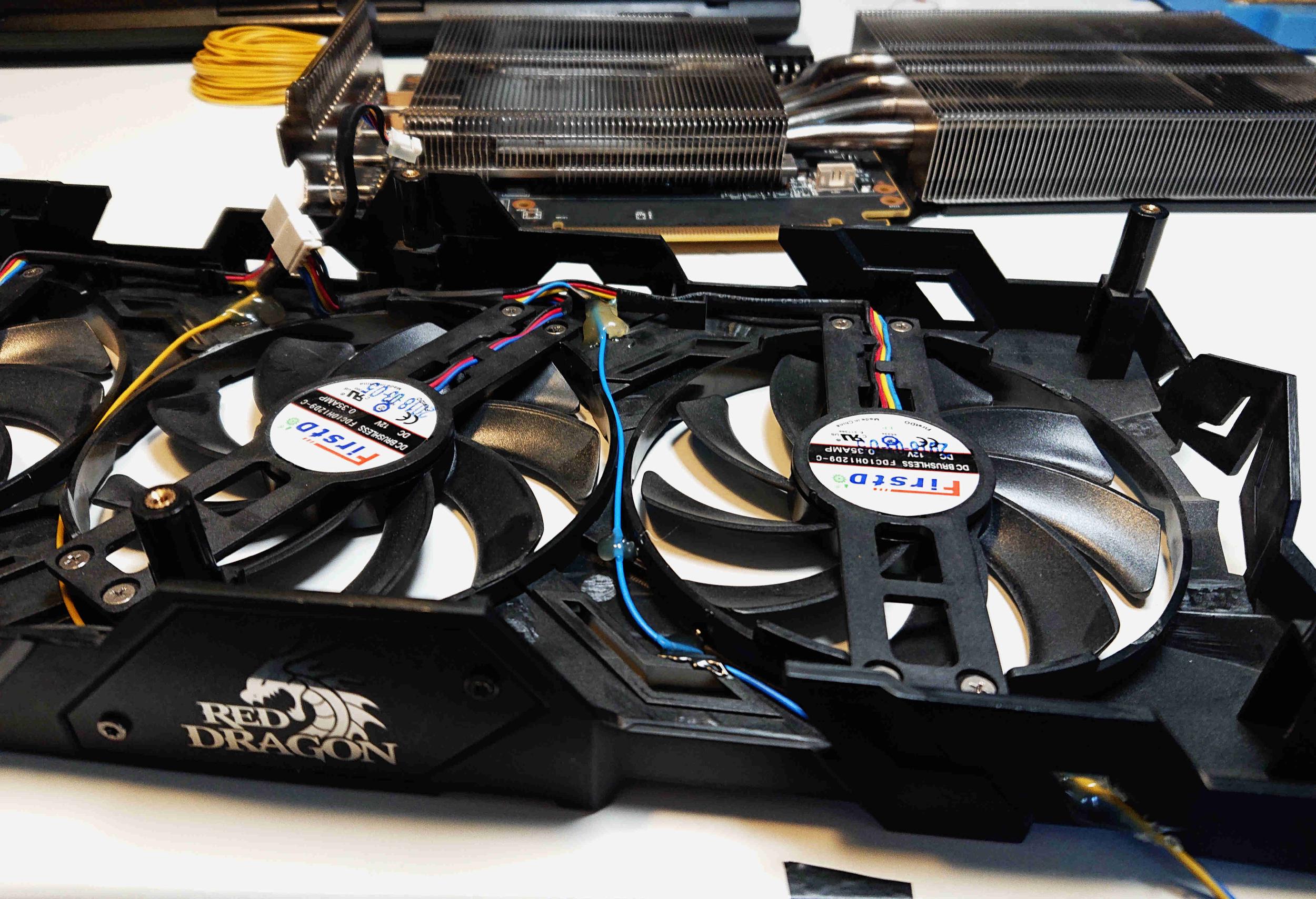
I acquired the CPU’s PWM signal in a similar fashion, although this time I just piggybacked on the motherboard connector. You might wonder why before the mainboard signal was deemed useless but now magically becomes useful again. This has two reasons: Firstly, the CPU fan I use doesn’t spin up very fast which also means the janky mainboard fan controller can’t really make it as loud and annoying as the case fans. Secondly, the thermal sensor that determines the CPU fan speed is positioned directly inside the die, thus giving a more realistic reading than the single case temperature sensor placed somewhere on the mainboard.
With the reference fan speeds now available, I moved on to actually measuring the PWM signal. PWM is just a rectangular wave so I set up a rising-edge interrupt on a GPIO that counts the triggers within one second. In theory this is easy but I ran into quite some signal deterioration which in turn led to false readings. I tried various things to get the signal into conformity and was finally successful by connecting a 15nF ceramic capacitor between the signal and ground. I compared the readings to those reported by the PC and they stayed within a few RPM which is more than accurate enough.
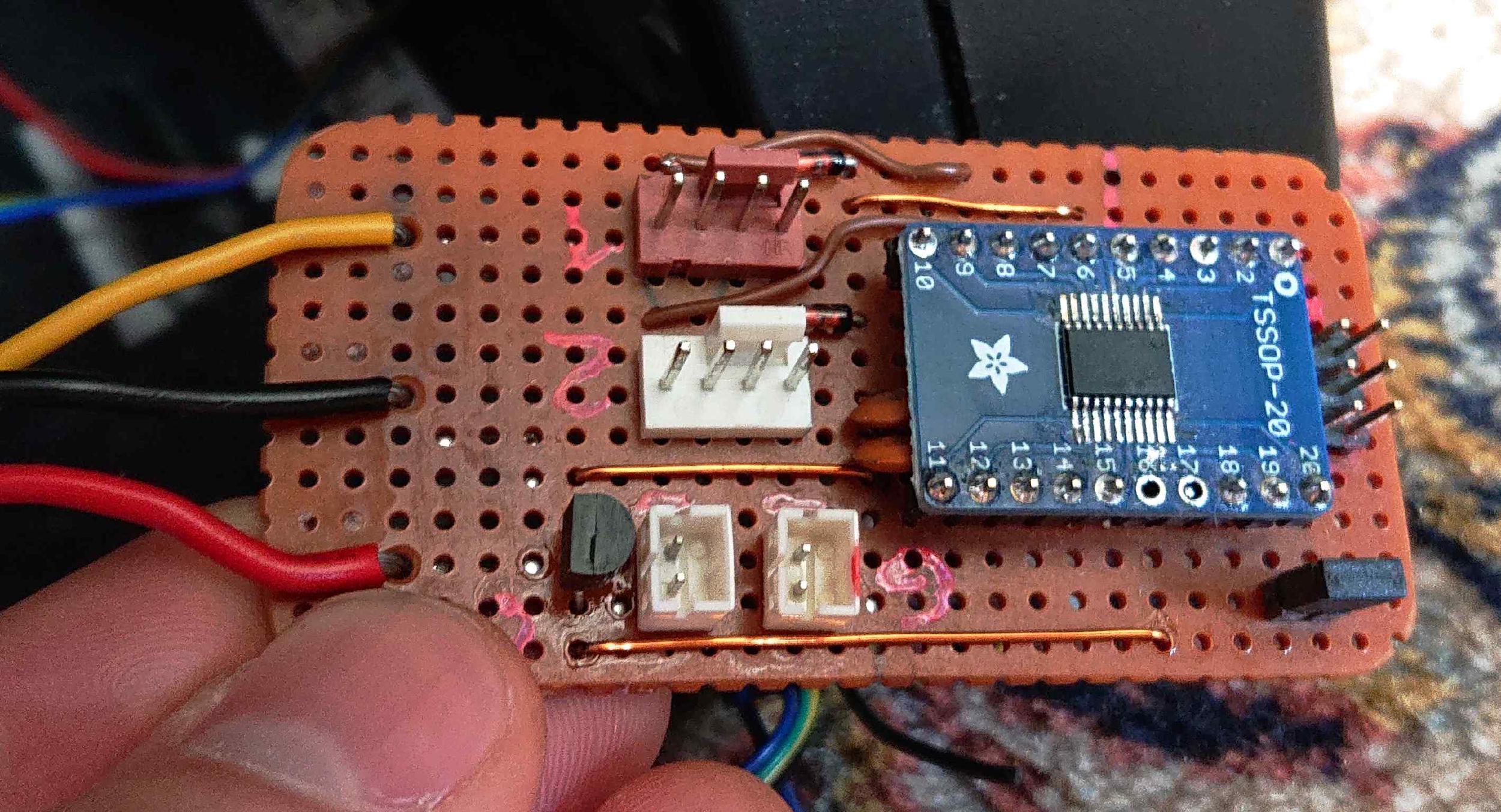
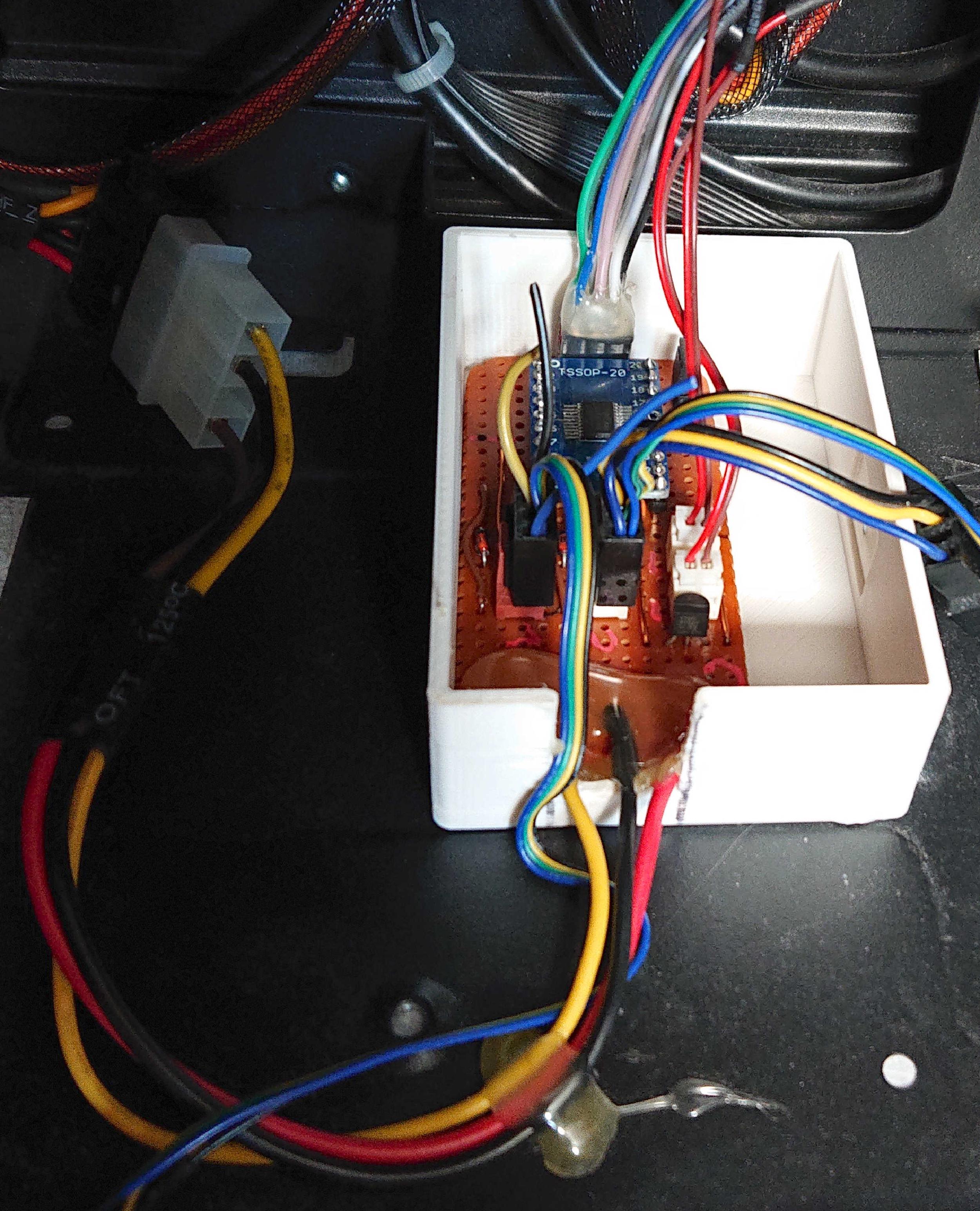
The fan controlling part was actually done beforehand. As usual, I started with an Arduino as for me it’s the quickest way to test something out. The Arduino was able to control the fan reasonably well but also created a high whining noise. Increasing the PWM frequency to shift it above the audible cut-off of 22 kHz would have worked, but then the fan no longer reacted. After some research I found that most PWM controlled fans adhere to a certain specification that dictates the PWM frequency to be between 21 and 28 kHz. Setting the Arduino’s ATmega 328P to a frequency in that range is possible, but it’s also a hassle and messes with the timers I needed. Instead, I just used the way more versatile STM32G031, an ARM Cortex-M0+ MCU. It’s incredibly overpowered for what I need it but I still had a few left from my Master’s thesis. I really like this chip as it’s one of the cheapest ARM MCUs you can get and still has a lot of computing power with pretty much all of the interfaces you’ll need. The TSSOP-20 footprints are very easy to hand solder, as well. Using the STM32 I got everything working flawlessly. The MCU is powered via the 5V rail from a Molex connector that a linear regulator knocks down to 3.3 Volts.
Software
With input and output sorted, I defined various fan output stages for thresholds of PWM inputs. So if the GPU fan is running at more than 1400 RPM, I set the case fans to run at 35 % speed. Both input signals are respected in determining the case fan stage. That means that if the GPU is idle, but the CPU is hard at work, the case fans will still spin up accordingly. I though about adding some kind of switch for enabling “power” or “summer” mode but eventually just left it like it is. The fans will reach 100% anyway and if that’s not enough to keep everything cool, a switch won’t have any effect anyway. I also took advantage of the ARM’s multiple PWM channels so that every case fan can have it’s own speed. For now though, I just tied them together as I rarely want them to spin at differing speeds.
Assembly
All that was left to do now is assemble the PCB and make it look somewhat neat. I used a strip of perfboard as the circuit isn’t very complex. I had some 3D printed cases left from my master’s thesis and used the upper part to have everything enclosed. Thanks to making everything modular I could just glue the case into the PC and then connect everything.
Due diligence
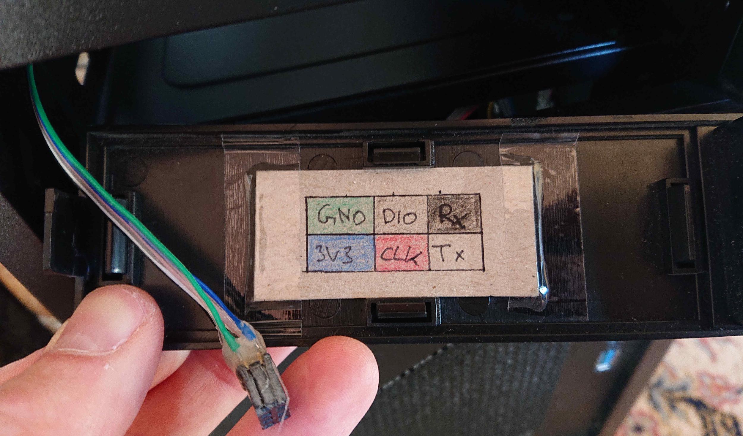
I was sure I’d forget the pin out for the debugging header I left on the PCB so I summoned all my kindergarten colouring skills and stuck a little pinout drawing to the inside of the case for future reference. The colouring matches that of the colours of the ribbon cable I left accessible for programming. Also, please appreciate the funky carpet pattern.
All in all it’s nothing fancy but it hopefully saves me from a few forced shutdowns caused by overheating.
You can find the schematic and code for this project in the corresponding git repository.